Documentation Index
Fetch the complete documentation index at: https://dev.docs.inworld.ai/llms.txt
Use this file to discover all available pages before exploring further.
Everything you can do in the Graph Editor can also be achieved by creating, editing, or removing
ScriptableObject assets.In highly customized scenarios, configuring via ScriptableObjects may offer finer control (for example, defining your own fields).The Graph Editor, however, is faster and requires less code.Create a Graph
You still need to create aScriptableObject for your graph.
In the Project tab, right‑click and choose “Create > Inworld > Graph > Default” or “Character Interaction”.
Fill in Required Fields
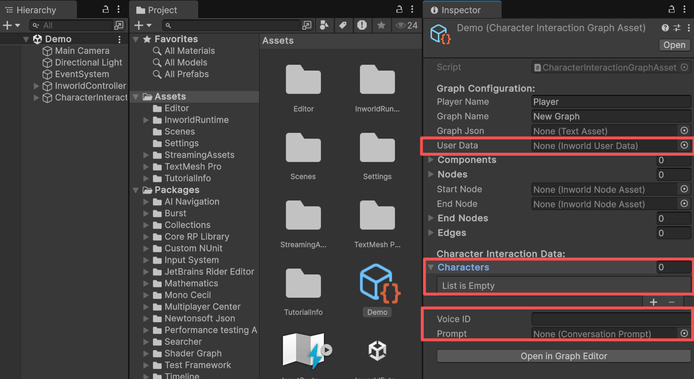
Do not open the Graph Editor yet. First, fill in some required fields, otherwise the graph will not run. The Default Graph is suitable for general tasks that are not related to character interaction. You can also inherit from Default Graph to implement more customized functionality. UserData is required.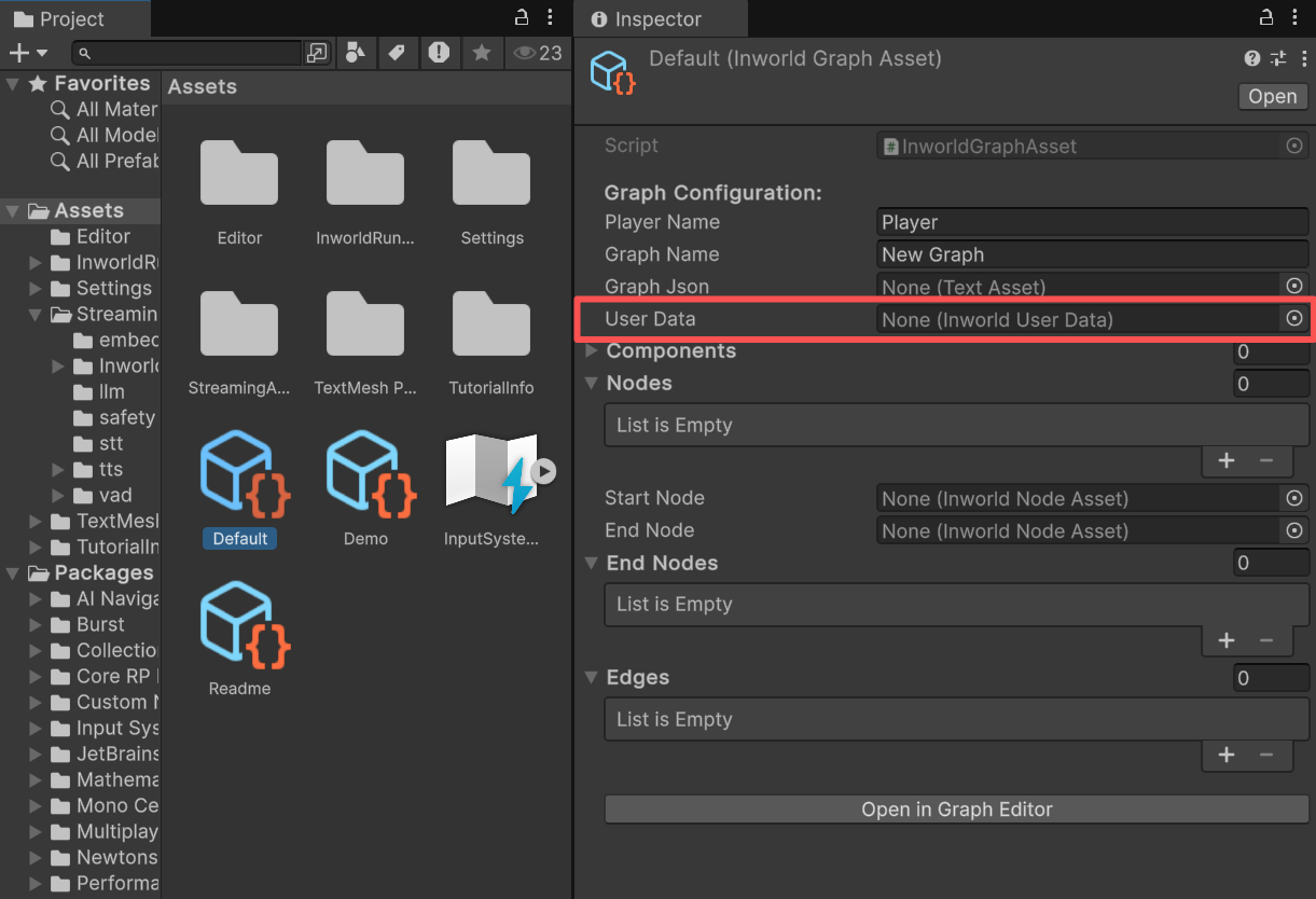
Voice ID.
If you plan to use an LLM node, provide a Prompt.
Zoom in Zoom out and Move Graph
You can scroll the mouse wheel to zoom in and zoom out. You can press and hold the mouse wheel to move around.
Create a Node
After opening the Graph Editor, right‑click inside the canvas and selectCreate Node.
You can add an Inworld node, or open Custom Nodes to add an existing custom node.
Create a New Custom Node Type
While adding a node, you can also selectCreate New Custom Node Script.
A dialog will appear asking for a file name and a path.
Click Create to proceed.
If the IDE configured for your Unity Editor is already open, it will switch to that IDE and open the newly created file.
Create an Edge
Drag from an output port of one node to an input port of another node to automatically create an edge.
Change Edge Type
Right‑click an edge to choose its type.
Delete Nodes or Edges
Select an edge and eitherRight‑click > Delete or press the Delete key.
Select a node and press the Delete key to remove it.
When you delete a node, any edges that can no longer connect will also be removed.

Save the Graph
Click Save Graph in the top left to save your changes to the current graph. You can also press “Ctrl + S” to do the same. After saving, ScriptableObjects for the nodes and edges are generated underAssets/Data/{Your graph name}.
The Start and End nodes are also computed and set automatically.
Export JSON
You can also clickSave Json to generate a JSON representation of the graph.
This feature is experimental; some component settings may be incomplete and may need to be filled in manually.