Overview
The Inworld Graph Editor (part of the InworldRuntime Unreal plugin) enables developers to build their graphs in Unreal using an easy-to-use visual editor. It lets you build graphs where nodes or subgraphs are connected by edges. Nodes/Subgraphs process data; edges define execution flow. Graphs are saved as assets and can be executed at runtime.Graph workflow summary
Editor Layout
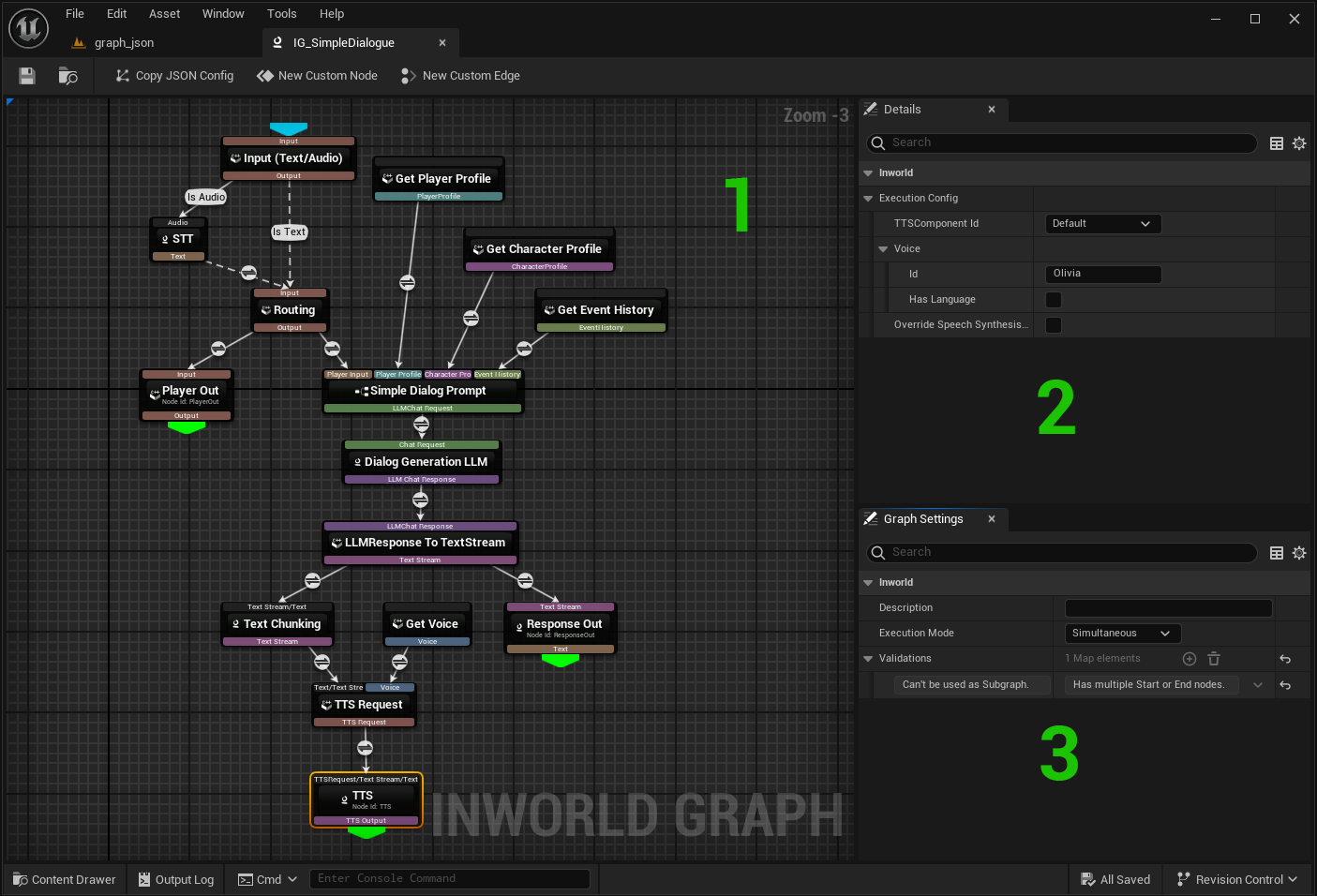
- Canvas — place and connect nodes. Drag to move. Ctrl+C/Ctrl+V to copy/paste. Del to delete node/edge.
- Details Panel (right) — properties of the selected node/edge.
- Graph Settings (below Details) — shows the description, execution mode and list of validation messages.
Execution mode defines how multiple executions are handled. Three modes are available::
- Simultaneous: Allow multiple executions to run simultaneously.
- Latest Only: Cancels previous execution when starting a new one.
- Sequential: Queues new executions until the current one finishes (FIFO), no cancellations.
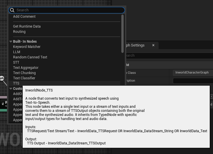
- Context Menu (right-click on canvas) — to add nodes, comment or subgraphs or on edge icon to define edge type.
- Start typing to filter by name.
- Hover a menu item to see its description, inputs/outputs.
Tooltips: Hover an input/output pin to see its data type in a tooltip.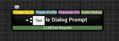
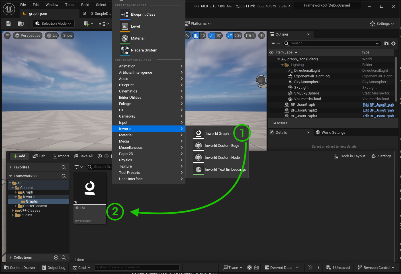
Creating a Graph Asset
- Add New > Inworld > Graph.
- Name and save the asset > Double-click to open Inworld Graph Editor.
Nodes
- Adding:
- right-click on the canvas and select a node from the menu.
- drag from a pin and release to open node selection menu. In this case, the menu is filtered to show only nodes that can accept the input of the dragged pin. (can be changed in the settings)
- Move/Copy/Paste/Delete: drag to move; Ctrl+C/Ctrl+V to copy/paste; select node Del to delete.
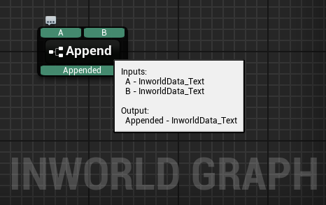
- Hover for Info: hover a node to see description and pins info.
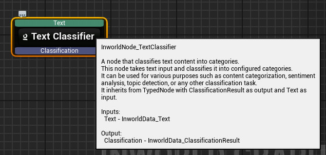
- Pins & Types:
- Each input/output pin has a data type (pins are color-coded).
- Optional inputs are indicated by * and noted in the tooltip.
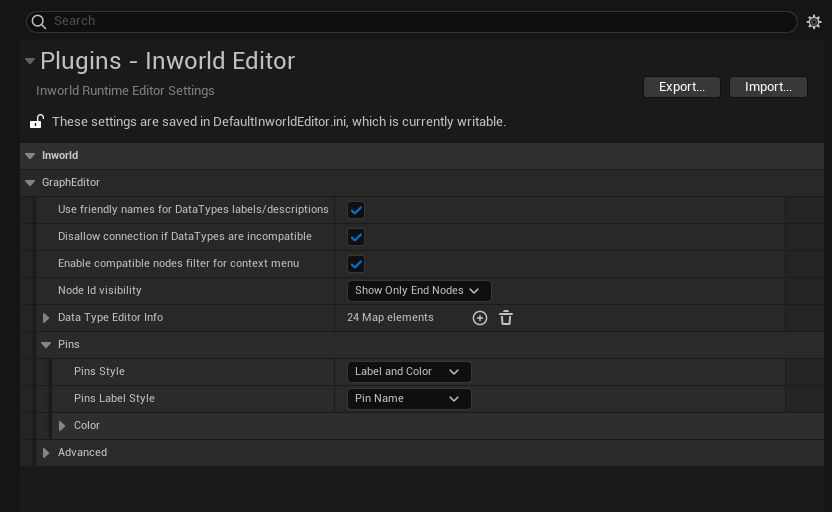
- Type checks prevent invalid connections; behavior configurable in Settings.
- Pin Display Modes (Settings): label + color, color only, or label only. Labels can show Pin Name or Data Type.
- Double-click node body > opens node implementation for custom nodes or subgraphs.
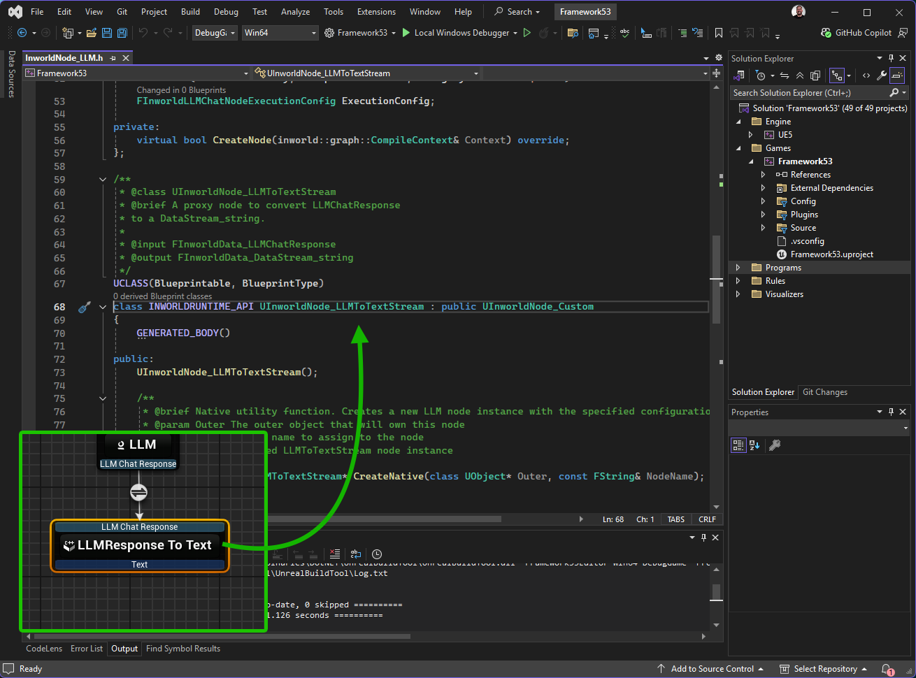
- Blueprint
- C++
- Double-click node name > rename the node inline.
- Getter Nodes: set IsGetter to true if no input required for node. In this case, you do not need to set up an input connection for the node. (optional you can wire input for explicit ordering).
Custom Node
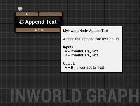
Custom nodes can be implemented using Blueprint or C++. In this example, we will implement a custom node that processes PlayerProfile RuntimeData and two Text inputs to combine them into one Text output.- Blueprint
- C++
-
Create Custom Node
Create via Content Browser or the New Custom Node button in the Graph Editor.
Custom nodes implemented in Blueprints have an icon
 in Graph Editor.
-
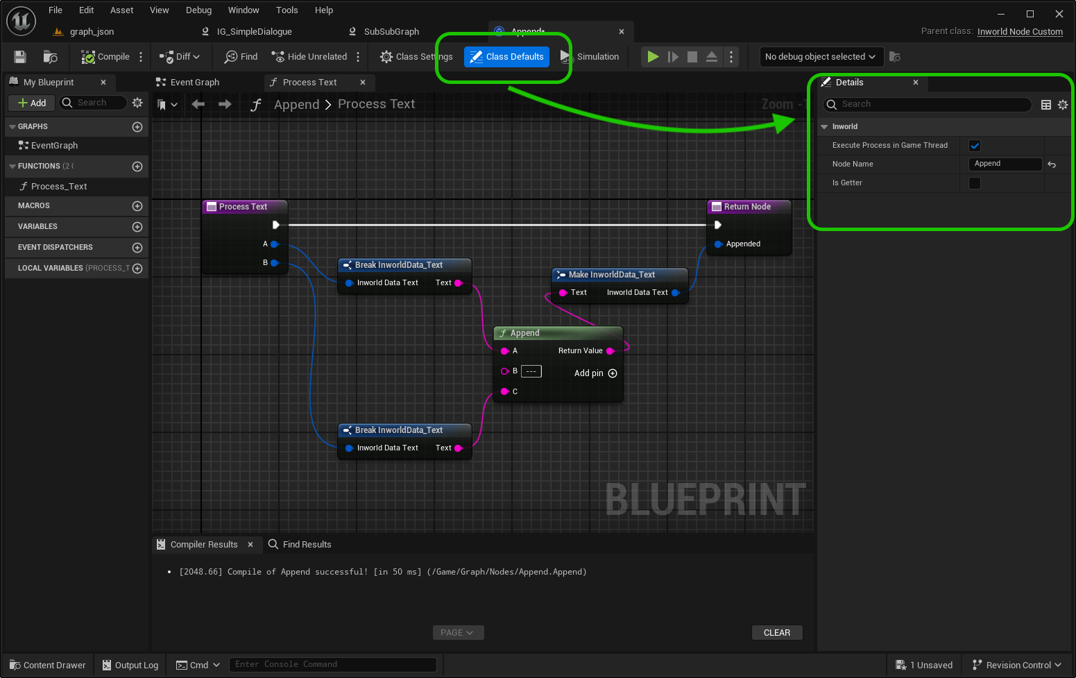
Class Defaults
Define:
- Node Name
- Node Description (Description of the node functionality and purpose)
- Is Getter (Special getter node mode that not required for input)
-
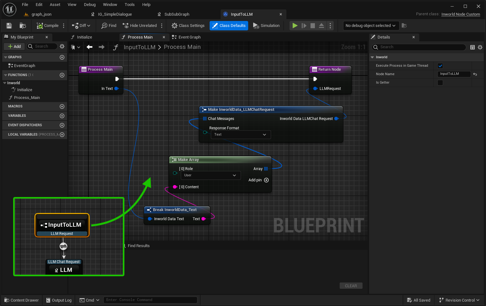
Process Function
To make a function available as a processing node, its name must start with Process.
Examples:
Process,ProcessDialogue,ProcessAudio,ProcessLogic. Each function defines the node’s execution logic. The defined inputs and outputs (names and types) are automatically reflected as pins in the Graph Editor. A single node can be linked to multiple processing functions. When executing, the node automatically selects the appropriate function based on matching input types.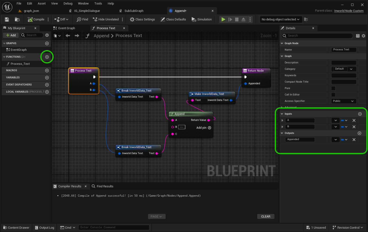
-
Save
The node appears in the context menu immediately.
Edges
- Connect by dragging between pins.
- Delete: select edge by click on icon > Del.
- Input/Ouput Types Checking:
- Disallow connection - checked (default): incompatible types cannot connect.
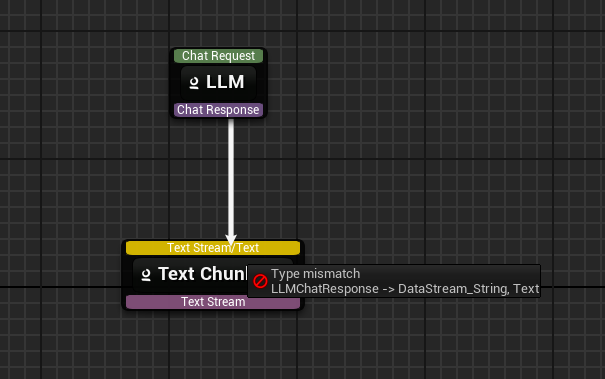
- Disallow connection - unchecked: connection allowed but a warning is shown.
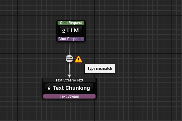
- Disallow connection - checked (default): incompatible types cannot connect.
- Conditional Edges:
- Set an edge type: right-click the edge > choose a Condition type (e.g., General, IsSafe).
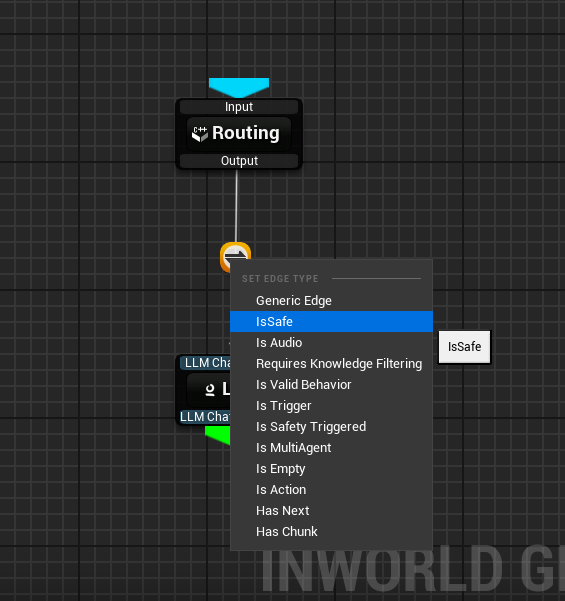
- Each condition can be negated at design time in the Details panel.
- IsSafe is a special condition based edge on a safe-node result.
- Set an edge type: right-click the edge > choose a Condition type (e.g., General, IsSafe).
- Edge Properties: Title, Negation, Required.
- Not Required edges are shown as dashed lines.
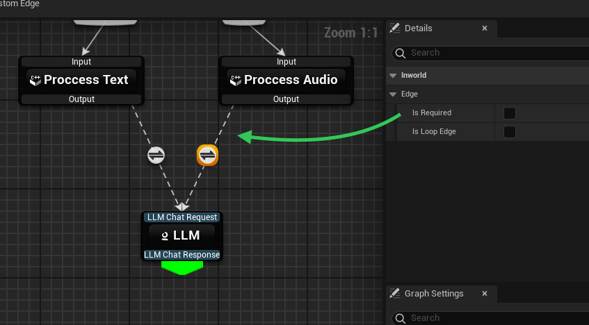
- To Open Implementation: double-click on conditional edge widget to navigate to implementation (C++ or Blueprint).
- Not Required edges are shown as dashed lines.
Custom Conditional Edge
Custom edges can be implemented using Blueprint or C++.- Blueprint
- C++
- Create Custom Edge Create via Content Browser context menu or the New Custom Edge button in the Graph Editor.
-
Class Defaults
Define:
- Edge Title
- Execute Meets Condition in Game Thread
-
MeetsCondition Function
To make a function available as a condition, its name must start with MeetsCondition.
Examples:
MeetsCondition,MeetsConditionCheck,MeetsConditionIsValid,MeetsConditionLogic. Each function defines the edge’s conditional logic and must return a bool value. A single edge can be linked to multiple condition functions. When executing, the edge automatically selects the appropriate function based on matching input type.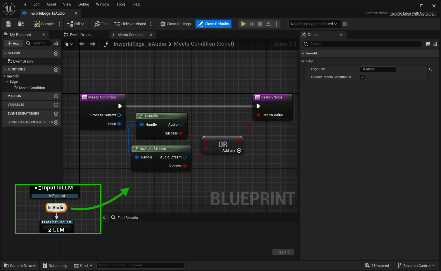
- Save The edge appears in the context menu immediately.
Start & End Nodes
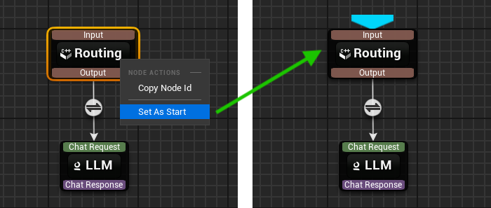
- Start Node:
- Mark a node as Start (right-click on node > Mark as Start).
- At runtime, all Start nodes receive the top-level input data you pass into
Execute(...)and RuntimeData. - A node with no incoming edges can be marked as a start point.
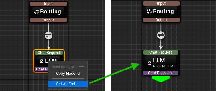
- End Node:
- Mark a node End (right-click on node > Mark as End).
- When an End node finishes, it emits a result callback carrying that node’s output.
- A node with no outgoing edges can be marked as an end point.
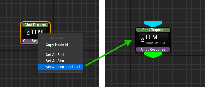
- Dual-role Node: A node with no inputs and outputs can be marked as both Start and End.
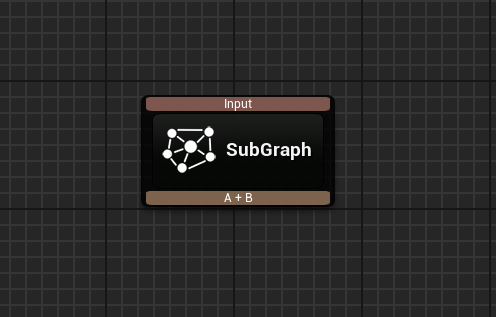
Subgraphs
Each saved graph asset that has exactly one Start and one End node can be added as a Subgraph to an existing graph as node. The subgraph’s inputs correspond to its Start node inputs, and its output comes from the End node. All RuntimeData is automatically passed to the subgraph during execution.- Adding:
- Right-click on the canvas and select a subgraph from the
Subgraphsection of the context menu. - Or drag from a pin and release to open the selection menu.
- Right-click on the canvas and select a subgraph from the
Settings
Executing a Graph using Graph Asset at Runtime
- Get an instance:
GetGraphInstance - Execute the graph: call
Execute().- Start nodes will receive
InputandRuntimeDatamap. - Each End node triggers
OnResultCallbackand returns the result along with the correspondingNodeIdandExecutionId.
- Start nodes will receive
- Process results in your system.
- Blueprint
- C++
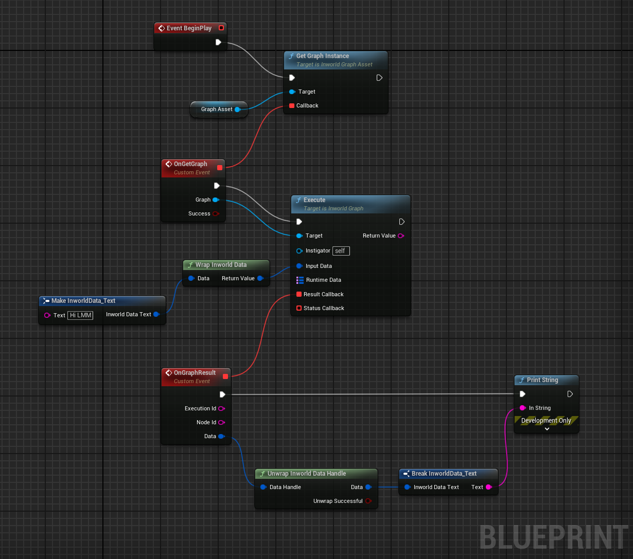
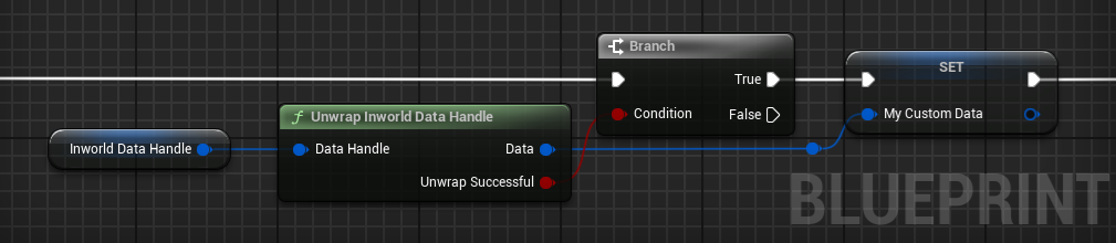
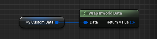
Inworld Data Handle
Graph input and result data must be of type FInworldDataHandle. Input data must be “wrapped” into FInworldDataHandle.- Blueprint
- C++
- Blueprint
- C++